Issue 5 - April 2014
Update 5 provides clarification and further information on technical issues relating to the residential guidance (Repairing and rebuilding houses affected by the Canterbury earthquakes). These issues result from new information or feedback received on the guidance since its publication in December 2012.
42. Schedule 1 of the Building Act 2004 was amended, effective 28 November 2013. Does the revised wording in Schedule 1 alter the advice provided in Appendix A3 on assessment and repair options for chimneys regarding the need for a Building Consent?
(Guidance document reference – Part A, Appendix A3)
Section A3.3 currently states:
The Ministry’s document Canterbury Earthquake Recovery Information for Home Owners and Building Practitioners – Building Work that does not require a Building Consent as at 20 September 2010 notes that repairing or replacing a chimney or flue does not require a building consent. [Note: This Ministry document has now been updated, refer to 19 March 2014 ‘Building Work that does not require a Building Consent’.
Chimney damage was widespread in Canterbury during the earthquake sequence. Demolition of the chimney does not require a building consent (pursuant to Schedule 1, Clause 31), provided that the building is not more than 3 storeys high and the removal does not affect:
- the primary structure of the building; or
- any specified system; or
- any fire separation.
Repair or reconstruction of the chimney may require a Building Consent depending on the degree of damage and the repair envisaged. You will need a building consent if the repair or replacement involves the “complete or substantial replacement of any component or assembly contributing to the building’s structural behaviour or fire-safety properties” as per Schedule 1 Clause 1(3)(b).
Schedule 1 Clause 1 provides an exemption for the repair or maintenance of any component or assembly incorporated in or associated with a building, provided that comparable materials are used. If the chimney has retained structural integrity and there is only minor repair work, then the general exemption for repair, maintenance, and replacement in Schedule 1(1) could apply.
The Clause 1 exemption could also apply where there has been damage to the upper part of the chimney’s height that is replaced with a metal flue system and light-weight surround as per the second heading of Section A3.7.2 of the Guidance. In this case it is considered that the assembly is comparable as it performs the same function and does not reduce compliance with the Building Code (ref. Building Act Section 42A(2)(b)), and it is not a complete or substantial replacement.
Note: The Clause 1 exemption will not apply if new or recycled bricks are to be used because of the heavy weight of the chimney, now acting as a single block, and the uncertainty about how the connection into the lower unreinforced part of the chimney may affect the structural performance of the building (per Schedule 1 (3)(b)). The Guidance does not recommend this approach and such a proposal would need to be considered on a case-by-case basis. A building consent will be required unless the Territorial Authority agrees to grant an exemption under Schedule 1 Clause 2, which provides the Territorial Authority the discretion to issue exemptions where “the completed building work is likely to comply with the building code; or if the completed building work does not comply with the building code it is unlikely to endanger people or any building”.
Substantial replacement of the chimney will also require a building consent unless the Territorial Authority agrees to grant an exemption under Schedule 1 Clause 2.
Christchurch City Council, for example, has a list of work they will consider under Clause 2, refer to Form B-391. This includes the removal and replacement of brick chimneys, irrespective of whether structure and cladding are comparable. For more information, please see the Christchurch City Council website
43. Is it acceptable to notch bearers and piles beneath an existing Type A or Type B dwelling to assist with the relevelling process?
(Guidance document reference – Part A section 4.3, Part A appendix A1, Part C section 14.2)
Yes it is acceptable to notch these elements, provided that they are notched within the limits detailed in this answer. It must be done as part of the floor relevelling where some jacking and packing is undertaken and the final resulting floor is overall no lower than it was prior to the relevelling process commencing. This ensures that Building Act section 112 is complied with in relation to Building Code Clause E1.
In a timber floor system the bearers support the joists and are in turn supported by the piles and/or perimeter foundation walls. If we consider each case separately, there are:
- ends of bearers
- mid-span supports of bearers
- ends of joists
- mid-span supports of joists.
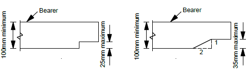
Case 1: Ends of bearers
The ends of 100mm and 125mm deep bearers may be notched by 20mm with a square cut transition. If the transition is sloped at 2 to 1 then the notch depth may be increased to 35mm. The remaining capacity of the bearer is adequate to take normal design floor loadings of 1.5kPa. On some occasions, engineers have chosen to use a steel shoe adjacent to the notch for added strength.
Case 2: Intermediate supports of bearer
Where bearers span over intermediate supports, they may be notched on the underside (compression) face of the bearer by 20mm over a maximum length equivalent to the pile width plus 50mm. 800mm long by 25mm thick side splice plates must be added, fixed at each end (5 - 100mm nails for 125mm deep bearer and 3 – 100mm nails for 100mm deep bearer). In this case, removal of some of the bearer depth will reduce the bending strength and stiffness. It is therefore necessary to add splice members to the sides of the bearer to recover the original bending strength at the notch. It is important that the splice elements also bear on the top of the pile for the splice to be effective.

Case 3: Ends of Joists
The ends of 100mm and 125mm deep joists may be notched by up to 20mm with a square cut transition. If the transition is sloped at 2 to 1 then the notch depth may be increased to 30mm. It is not necessary to add a metal shoe to the joists. Notching the ends of joists is similar to the ends of bearers except that the loads at the notch are less. Most joists in Type B floors are 125mm deep but there will be instances where they are 100mm deep. The above limits may be applied to joists deeper than 125 mm. Specific designs may allow deeper notches in these sizes.
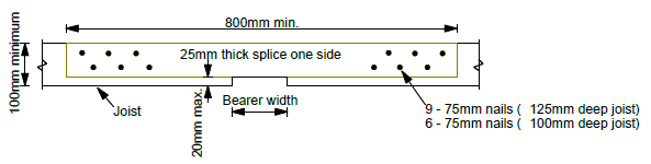
Case 4: Intermediate support of joists
At intermediate supports, 100mm and 125mm deep joists may be notched up to 20mm with a square cut transition. An 800mm long by 25mm thick side splice is required to be fixed to each joist at the notched crossing (9 – 75mm nails each end for 125mm deep joist and 6 – 75mm nails each end for 100mm deep joist). In this case, removal of some of the joist depth will reduce the bending strength and stiffness. It is therefore necessary to add splice members to the sides of the joist to recover the original negative bending strength at the notch. It is important that the splice elements also bear on the top of the bearer for the splice to be effective.
44. For the TC3 Type 2A-300 and 2B (refer to Q&A 38 and Q&A 46) surface structure foundations, because the piles are cantilevering from the concrete slab, is it necessary to have the plywood skirt around the perimeter of the foundation?
(Guidance document reference – Part C section 15.4.3)
The plywood skirt was originally specified when the Type 2A-300 and 2B surface structure foundation designs were developed by MBIE because of a concern that there may be some “shrinkage slop” of the piles in the slab. The overall structural strength of the system would not be affected by this but there may have been some small rotation of the pile at service loads. Observations of completed Type 2B foundations have shown that the piles are well anchored in the slab and therefore there is no need for the plywood skirt. The need for a plywood skirt on Type 2A-150 foundations will be reviewed based on further field observations.
The designer must still design and document requirements to address aesthetic and architectural details and code compliance issues such as weathertightness, subfloor ventilation, and durability.
45. For TC3 Type 2A and 2B surface structure foundations, are there alternative ways of finishing the perimeter of the slab and perimeter subfloor cladding?
(Guidance document reference – Part C, Section 15)
Consideration has been given to providing another detail that has the edge of the slab in the same vertical plane as the cladding line above, and enables the slab to be cast at a level slightly above the surrounding ground level.
The TC3 Type 2A and 2B foundation options were developed on the principle that the timber piles cantilevered from the slab, thus providing the lateral support for the superstructure under wind and earthquake loading. All piles are expected to introduce a bending action to the slab under lateral loading.
Figures 15.19 to 15.21 of the Guidance indicate that the slab should extend 500mm beyond the exterior row of piles. If the joists and bearers are cantilevered beyond the bearer or the last pile in the row respectively, then it is possible to cover most of the extension. However, it has been determined that a reduction in the joist size to 140 x 45mm and a change in the bearer size to 2/140 x 45mm members is a more economic option for these structures. This means that the span (a maximum 2.7m clear span when at 400mm centres) is less than a 190 x 45mm joist can span and extra rows of piles will be required. It also means that the overhang of the joist on the bearer (the cantilever) may only be 150mm. This is suitable for both single and two storey houses with light roofs and either light or medium weight wall cladding.
Water should not be allowed to pond beneath the floor of the completed dwelling. Therefore, the ground level under the house (Type 2A) and the top surface of the slab (Type 2B) should be set at a level that is higher (approximately 50mm) than the surrounding land.
The new details for the Type 2A and Type 2B under-slab in TC3 have been developed as shown in the following figures. These details should be read in conjunction with Figures 15.19 to 15.21 of the Guidance.
(See also Q&A # 44 on the deletion of the plywood skirt on TC3 Type 2 foundations)

Table 1: Maximum distance between top of slab and underside of joist (m)
| (150mm slab) | (300mm slab) | |
| Single storey light weight wall/light roof | 1.00 | 1.15 |
| Single storey medium weight wall/light roof | 1.00 | 1.00 |
| Two storey light weight wall/light roof | 0.75 | 0.75 |
| Two storey medium weight wall/light roof | 0.60 | 0.60 |
46. There have been some changes to the descriptions of the TC3 Type 2 surface structure foundations in the Guidance. Can you please provide a summary of the available Types and their specifications?
(Guidance document reference – Part C section 15.3)
The Guidance provides details for a Type 2A and a Type 2B surface structure foundation. The Type 2A has a 150mm concrete under-slab and the Type 2B has a 300mm under-slab. Both had a 600mm reinforced gravel layer included beneath the slab. Q&A # 38 extended the guidance for Type 2A to allow, as an alternative, a 300mm slab to be used in the better areas of TC3 (where the SLS settlements were <100mm) without the need for a 600mm reinforced gravel layer.
For greater clarity, the Type 2 surface structure systems have been re-named as follows:
| Identifier | Description | Maximum calculated SLS settlement (mm) |
| (refer to Figure 1) | A 150mm concrete under-slab in combination with a 600mm reinforced gravel layer (refer to Figure 15.19) | 100mm |
| (refer to Figure 2) | A 300mm concrete under-slab, reinforced as per type 2b slab over a 150mm layer of compacted well graded sandy gravels extending 500mm beyond the edge of the slab and with a geotextile layer under the compacted gravel. The geotextile layer is to be turned up at the ends of the gravel layer and returned a minimum of 1m under the slab. | 100mm |
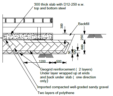
| (refer to Figure 3) | A 300mm concrete under-slab in combination with a 600mm reinforced gravel layer (refer to Figure 15.20) | 200mm |
Figure 1: TC3 Type 2A-150 Foundation
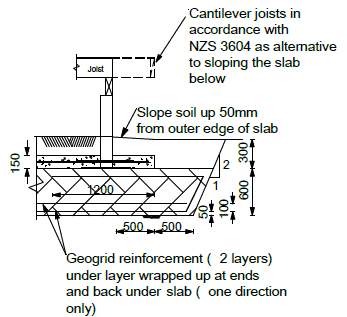
Figure 2: TC3 Type 2A-300 Foundation
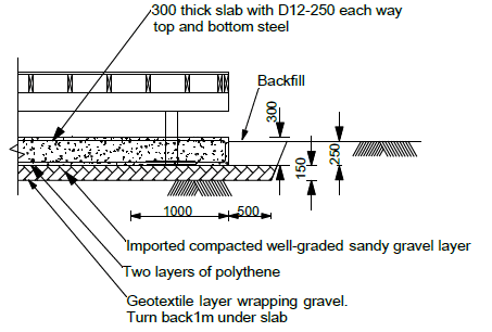
Figure 3: TC3 Type 2B Foundation
For multi-unit buildings (MUBs), a range of similar style foundation systems has been developed. The special conditions associated with MUBs have meant that the gravel layer has a different function from the raft beneath a detached house. Details are provided in Part E Table 20.1.
Repairing and rebuilding houses affected by the Canterbury earthquakes