Issue 7 - October 2014
Update 7 provides clarification and further information on technical issues relating to the residential guidance (Repairing and rebuilding houses affected by the Canterbury earthquakes). These issues result from new information or feedback received on the guidance since its publication in December 2012.
50. Now that the new report UCD/GCM-14/01 “CPT and SPT Based Liquefaction Triggering Procedures” by R Boulanger and I Idriss (2014) has been published (and is available at CPT and SPT Based Liquefaction Triggering procedures), can this liquefaction analysis methodology be substituted for the Idriss & Boulanger (2008) method cited in the MBIE guidelines?
Yes, the Boulanger & Idriss (2014) deterministic methodology can be optionally substituted for the Idriss & Boulanger (2008) methodology when using the MBIE guidelines for sites in the Canterbury earthquake region, provided the following requirements are met:
- At SLS for sites in the Canterbury earthquake region, both the M7.5 / 0.13g and a M6 / 0.19g design case must be analysed (and the highest calculated total volumetric strain from either scenario adopted).
- At ULS it will be sufficient to simply analyse the M7.5 / 0.35g case for sites in the Canterbury earthquake region.
- If fines contents are being derived from CPT data, the new FC / Ic relationship in the 2014 methodology is to be adopted. A CFC fitting parameter of 0.0 should be used, unless appropriate lab data or other evidence supports a different value. For example, Robinson et al (2013) suggests a value of CFC = -0.07 could be adopted for liquefiable soils along the Avon River.
For sites outside of the Canterbury earthquake region, it would only be appropriate to adopt the 2014 methodology where a seismic hazard deaggradation plot or other data has been examined to determine appropriate representative design events.
While for consenting purposes this updated methodology is currently optional, it is recommended that engineering practices begin phasing in this method (where it is applicable) as soon as is practicable. It is not intended that previously written geotechnical reports are necessarily revisited. Once the 2014 methodology has been adopted by an engineering practice, it is not appropriate to switch back to the 2008 methodology for subsequent projects.
Background
The 2014 method is an update to the 2008 method, incorporating additional liquefaction case history data (much of it derived from the Canterbury Earthquake sequence) and a re-fitting of the analysis methodology to that updated data set. 50 Christchurch case histories have been added to the database and Christchurch now accounts for 20% of all data points. The main changes are:
- A new formulation for magnitude scaling factor (MSF).
- Details of the formulation for the equivalent clean sand adjustment for fines content (for CPT data, but not for SPT data).
- Details of the formulation for the derivation of cyclic resistance ratio (for CPT data, but not for SPT data).
- A revised relationship between Ic and fines content.
Of these updates to the overall methodology, all but the first one (MSF) presents little difficulty in the adoption of the 2014 analysis method. However the new formulation of the magnitude scaling factor is a significant departure from the methods commonly used to date. The new MSF formulation now not only relates to earthquake magnitude but also varies with the density of the soil (ie qc1Ncs or (N1)60cs – refer to Figure 2.6 below, taken from UCD/GCM-14/01 “CPT and SPT Based Liquefaction Triggering Procedures” by R Boulanger and I Idriss (2014)).
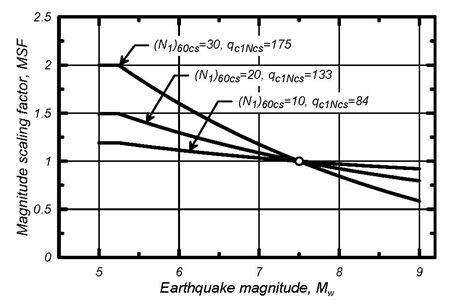
Figure 2.6. Variation in the MSF relationship with qc1Ncs and with (N1)60cs for cohesionless soils
At M7.5 the MSF is still equal to 1.0 for all soils, using the new formulation. However convenient this might at first appear (given that the New Zealand SLS and ULS design accelerations for liquefaction are derived for equivalent M7.5 events), for actual events that differ from M7.5, the new MSF can vary significantly depending on the density of the soil. For an M6 event for example, for which the 2008 MSF would be about 1.5, the 2014 MSF will vary from 1.6 for a soil with a qc1Ncs of about 175, to 1.1 for a soil with a qc1Ncs of about 80.
Using the 2008 analysis method, a design event of M7.5 and 0.13g will give similar analysis outcomes (in terms of liquefaction triggering and calculated volumetric strain) as design events of M6 and 0.19g, or M8 and 0.11g. Using the 2014 formulation however, quite different outcomes can occur depending on the density of the soil. Using the example in the preceding paragraph, a soil which previously was calculated to have a factor of safety (FOS) of 1.0 against liquefaction triggering could now in fact have a FOS that varies from 0.75 to 1.1 for an M6 event, depending on the density of the soil. Given that volumetric strain occurs up to a FOS of 1.5, the difference in calculated settlement can be significant.
This means that if the 2014 method is adopted, continuing to use the ‘universal’ M7.5 design events at SLS and ULS is no longer necessarily appropriate, given the higher probability of occurrence of an event in the order of M6 in the Canterbury earthquake region. The implications of this in the 2014 methodology are particularly evident for the SLS event, for typical Christchurch conditions. At ULS levels of shaking, the differences are quite muted and therefore it is not considered necessary to carry out a separate M6 calculation at that level of shaking.
In theory, a large number of magnitude/pga combinations could be assessed for any particular site, as a large number of fault rupture scenarios are possible, and are present in the probabilistic seismic hazard model that is used to derive the design event. This is not a practical approach however. Instead, it is considered appropriate to analyse the most likely SLS design scenario magnitude (as well as the M7.5 standard design event). Based on a deaggradation of the seismic hazard for Christchurch and comparisons of settlement estimates obtained using both the 2008 and the 2014 methods, a nominal event of 0.19g at M6 has been determined as a ‘representative’ SLS design event. For other geographical locations the representative event will be different, and in some locations more than one event might be appropriate, depending on the local seismicity.
References
- Boulanger, R. W., and Idriss, I. M. (2014). "CPT and SPT based liquefaction triggering procedures." Report No. UCD/CGM-14/01, Center for Geotechnical Modeling, Department of Civil and Environmental Engineering, University of California, Davis, CA, 134 pp.
- Idriss, I. M., and Boulanger, R. W. (2008). Soil liquefaction during earthquakes. Monograph MNO-12, Earthquake Engineering Research Institute, Oakland, CA, 261 pp.
- Robinson, K., Cubrinovski, M., and Bradley, B.A. (2013). "Comparison of actual and predicted measurements of liquefaction-induced lateral displacements from the 2010 Darfield and 2011 Christchurch Earthquakes." Proc. 2013 Conference of the New Zealand Society for Earthquake Engineering (NZSEE 2013), Wellington, New Zealand, 26-28 April.
51. The updated Boulanger & Idriss (2014) method includes a probabilistic approach to liquefaction analysis. Can this probabilistic approach be utilised where the MBIE guidelines are being used?
The standard deterministic liquefaction assessment method in both Idriss and Boulanger (2008) and in the updated Boulanger & Idriss (2014) methods (as well as other methodologies from other authors), incorporate a threshold probability of liquefaction PL of 15%. The use of that threshold probability should be continued when using either method for assessing liquefaction under the MBIE guidelines. However, on ‘well tested’ sites where settlement calculations do not correlate well with observed damage or actual settlements, and a decision is being considered to favour site observations over calculated settlements, an examination of calculated settlements at a higher threshold PL (for example PL = 0.5) may give further guidance to the engineer in making that judgement.
52. Is it acceptable to build up the top surface of an existing Type B perimeter foundation to create a horizontal surface on which to build a new veneer that is correctly aligned with the window sills and soffit?
(Guidance document reference – Part A, sections 2.2 and 2.3)
Yes it is acceptable to build up the perimeter foundation of a Type B house to provide a level surface on which to build a new veneer as long as the foundation is still in good condition and does not need to be replaced (refer Table 2.2 or Table 2.3 of the MBIE guidance for re-level/rebuild indication criteria). This will allow the aligning of the veneer with the window sills and the soffits after relevelling the floor using jack and pack methods.
In order to build up the foundation, the existing veneer will need to be removed and replaced. While the veneer is removed the home owner may choose to install insulation in the wall framing but this is optional for the homeowner and is not a regulatory requirement.
To create a horizontal surface for an existing Type B perimeter foundation, use the following procedure.
| Step | Action |
| 1 | Remove the brick veneer. |
| 2 | Undertake any crack repairs on the existing foundation (see Appendix A4 for crack repair guidelines). |
| 3 | Clean and roughen the top surface of the foundation. Note: This ensures that there is a good bond between the old and the new work. |
| 4 | Use timber formwork (eg plywood with foam grout seal to existing wall face) to contain the levelling material. |
| 5 | To create the new level top surface for the veneer use either epoxy grout, mortar or cement grout, depending on thickness of filler required.
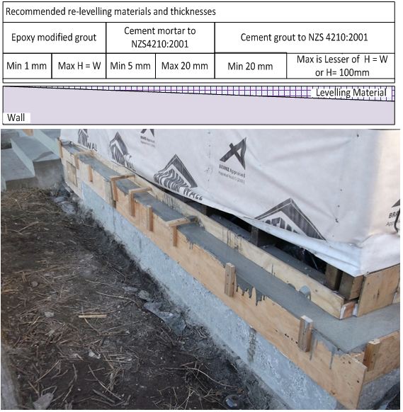 |
| 6 | Roughen the top surface of the grout to ensure a good bond with the veneer bedding mortar course. |
| 7 | Replace cladding with a modern 70 series veneer which has a significant reduction in weight over the old veneer.
Note: Other lighter cladding materials may also be used provided that they are appropriately installed to ensure that all relevant clauses of the Building Code are satisfied. |
| 8 | Fix the new veneer to the framing according to the requirements of Table 18A of Building Code clause E2/AS1.
Note: The ties provide all of the required lateral load resistance for the veneer and the perimeter foundation only provides gravity support for the veneer. |
| 9 | Limit the ratio of the filler height over the foundation beam width to one, or 100 mm, whichever is the lesser amount.
Note: If heights are greater than 100mm then specifically designed mechanical fixings should be used. 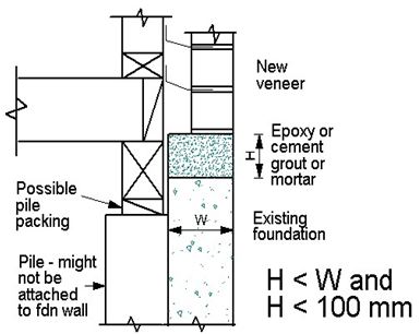 Figure 1: Section elevation; width to height ratio of wall extension |
| 10 | If the veneer is positioned back from the outside edge of the wall, a chamfer may be created at the junction between the veneer and the foundation beam. |
| 11 | Coat the outside face of the foundation with plaster to provide a clean finish. |
53. When designing a Type 1 foundation, the MBIE Guidance document indicates a pile foundation depth of 350mm. Is there a maximum depth, or criteria, for the footing depth?
(Guidance document reference – Part C, Figure 15.16 and Table 15.6)
Yes there is a specific footing depth of 350mm below ground level as shown on Figure 15.16 in the MBIE guidance. The thickness of concrete below the pile should be 100mm.
The reason for this is that shallow piles such as these around the perimeter of the foundation, braced by the plywood cladding, are capable of displacing the soil should the ground spread beneath the building as shown on Figure 15.16. This specific footing depth is required on all piles of the Type 1 foundation. The Type 1 foundation is able to be used on sites where the lateral spread is expected to be less than 200mm in a ULS event and there is no expectation of significant lateral spread in an SLS event (see Table 15.6). Unbraced piles in the Type 1 foundation are expected to lean over up to 100mm in a ULS earthquake and may require replacement after the event.
Repairing and rebuilding houses affected by the Canterbury earthquakes